Design Question: Counter that Skips Every Multiple of 3
Design a counter that starts at 1 and outputs a new value on every clock cycle, but it must never output a multiple of 3. The sequence looks like this: 1, 2, 4, 5, 7, 8, 10, 11, 13, 14 … — every third number is skipped.
When most students first see this, they read it as a divisibility problem. The logic seems straightforward: count up by one each cycle, check whether the new value is divisible by 3, and skip it if it is. That check is a modulo-3 operation — and in software, that is exactly how you would write it.
In theory, the approach is correct. It produces the right sequence. But correct code and practical hardware are not the same thing, and a modulo operation is where the two part ways. Division is one of the most expensive blocks you can put on a chip. So before writing a single line of RTL, it is worth asking a simpler question: do we actually need to divide at all?
Hardware Design Thinking
This is where hardware design thinking comes in. Instead of asking "is this number divisible by 3?", look at the sequence the problem actually asks for and find the pattern in it.
Write out the outputs and look at the step from one value to the next:
1 → 2 is +1
2 → 4 is +2
4 → 5 is +1
5 → 7 is +2
The increment alternates: +1, +2, +1, +2 — and it never breaks.
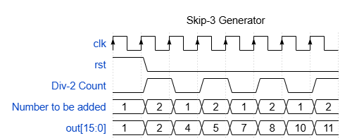
The reason is simple. Multiples of 3 are spaced exactly three apart, so between any two of them sit exactly two non-multiples. A step of +1 walks across those two; a step of +2 jumps over the multiple. Alternate the two, and you generate every value the problem asks for without ever landing on a multiple of 3.
Notice what just happened. The divisibility test disappeared. No modulo, no comparison, no division — only addition. The hard part was never the arithmetic. It was reading the sequence instead of reacting to the word "divisible."
Implementation Details
The whole circuit is just three small pieces. Take a look at the block diagram below.
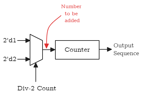
The div-2 counter. Start with a single flip-flop that toggles on every clock: 0, 1, 0, 1, … This is nothing more than a divide-by-2 of the clock, which is why the diagram labels it the Div-2 Count. Its only job is to remember which increment we owe this cycle — a +1 or a +2.
// Toggles every clock. Drives the mux select.
logic div2;

always_ff @(posedge clk)
begin
    if (rst)
    begin
        div2 <= 1'b0;
    end
    else
    begin
        div2 <= ~div2;
    end
end
The mux. The two increments are constants, 1 and 2, wired to the inputs of a 2:1 mux. The Div-2 Count drives the select line: when it is 0, the mux passes 1; when it is 1, it passes 2. The mux output is the "number to be added" for this cycle, and it takes a single assignment.
// div2 = 0 -> add 1;  div2 = 1 -> add 2
logic [1:0] add_val;
assign add_val = div2 ? 2'd2 : 2'd1;
The counter. Finally, the counter holds the running value. On reset it loads 1, and on every clock after that it adds whatever the mux handed it. Its output is the sequence the problem asked for.
logic [15:0] count;

always_ff @(posedge clk)
begin
    if (rst)
    begin
        count <= 16'd1;
    end
    else
    begin
        count <= count + add_val;
    end
end

assign out = count;
That is the entire design. No divider, no divisibility check, no comparison — just a toggle, a mux, and an adder. The critical path is a single addition, the same as an ordinary counter. You met a spec that looked like it demanded division using nothing but an add and a flip-flop that flips.
Alternate Methods
The div-2 counter and mux are the lightest way to generate the alternating increment — but they are not the only way. Two alternatives are worth knowing, because they generalize better when the skip pattern gets more complicated.
A rotating register (ring counter). Instead of computing the increment, store it. Load a small circular register with the pattern of increments — here just two entries, 1 and 2 — and rotate it one position every clock. The value at the head of the register is the number to add. For skip-3 the register is two deep, so it simply presents 1, 2, 1, 2, … The idea scales, though: if the pattern were longer or irregular, you would make the register deeper and load the right sequence into it. The control logic never changes.
// Two-entry rotating register: presents 1, 2, 1, 2, ...
// inc[0] is the head = the number to add
logic [1:0] inc [1:0];

always_ff @(posedge clk)
begin
    if (rst)
    begin
        inc[0] <= 2'd1;
        inc[1] <= 2'd2;
    end
    else
    begin
        inc[0] <= inc[1];
        inc[1] <= inc[0];
    end
end
A state machine. The same alternation can be written as a tiny FSM. One state emits +1 and moves on; the next emits +2 and moves back. The state register replaces the div-2 counter, and the output logic replaces the mux. For two steps this is heavier than it needs to be, but it is the most general of the three — an N-step skip pattern is just an N-state machine, and irregular patterns are easy to express.
// ADD1 -> ADD2 -> ADD1 ...
typedef enum logic {ADD1, ADD2} state_t;
state_t state;

always_ff @(posedge clk)
begin
    if (rst)
    begin
        state <= ADD1;
    end
    else
    begin
        if (state == ADD1)
        begin
            state <= ADD2;
        end
        else
        begin
            state <= ADD1;
        end
    end
end

assign add_val = (state == ADD1) ? 2'd1 : 2'd2;
Trade-offs
Every one of these designs produces the exact same output. The difference is in what they cost, and how well they hold up when the problem changes.
Divider vs. pattern. The modulo approach is the most general — it works for any modulus, no thought required — but you pay for that generality with a divider: a large block, a long critical path, and timing that fights you as the width grows. The pattern-based designs give up that generality in exchange for almost nothing — a flip-flop or two and a single adder, with a critical path no longer than an ordinary counter. For a fixed, known skip rule, that trade is almost always worth it.
Once you commit to reading the pattern, the choice comes down to how complex that pattern is, and whether it might grow:
- Div-2 counter + mux — smallest and simplest. Best when the increment alternates between just two values, like skip-3.
- Ring counter — store the increment sequence and rotate it. Pays off when the pattern is longer but still periodic; you just make the register deeper.
- State machine — the most general. Reach for it when the pattern is irregular, or when you expect it to change.
The counter and its single-adder datapath stay the same in all three. Only the logic feeding the "number to be added" changes.